I remember having this exact issue then getting bored and distracted and moving on.
Wishing you better luck lol.
22.10.2025 20:23 — 👍 0 🔁 0 💬 0 📌 0


Trying to take pictures of the sky.
28.09.2025 17:36 — 👍 1 🔁 0 💬 0 📌 0
Great.
Totally fine that fetish posts appear not only in the discover feed, but on the main feed as well “from discover” in my main feed as well.
I won’t be reading this app in public anymore :(
15.07.2025 17:06 — 👍 0 🔁 0 💬 0 📌 0
IIRC it was the connector itself because the other board worked.
31.05.2025 15:09 — 👍 1 🔁 0 💬 0 📌 0
That is super likely to happen, so maybe I do need a different approach.
I'll probably end up back at 0603.
02.05.2025 14:08 — 👍 0 🔁 0 💬 1 📌 0
Unfortunately at the moment time and money are in short supply.
I definitely want to revisit it though.
28.04.2025 14:56 — 👍 1 🔁 0 💬 2 📌 0
I remember getting a bunch of parts to make my own, but I guess I got distracted.
The unmodified toaster oven remains in the closet.
Problem is that making proper software to handle reflow profiles was going to take too long and I couldn’t afford a premade controller.
28.04.2025 14:55 — 👍 3 🔁 0 💬 1 📌 0
There's probably a tonne of them out there, it's always just a matter of time, money, or both.
It feels like one of those things where to do it properly is going to cost $100+ in parts or hours of code plus $50 in parts.
28.04.2025 14:12 — 👍 1 🔁 0 💬 1 📌 0
That looks so cool but the price is far beyond what I can afford right now.
Someday...
28.04.2025 13:03 — 👍 0 🔁 0 💬 0 📌 0
All I have is a toaster oven, but I haven't gotten around to buying a reflow controller for it yet.
28.04.2025 13:02 — 👍 1 🔁 0 💬 1 📌 0
Just curious how feasible manual pasting and hot air soldering of 0402 parts is.
They look terrifyingly small.
26.04.2025 15:31 — 👍 3 🔁 0 💬 4 📌 0
What a ride…
On one board I lifted the usb connector because I’m clumsy, and on the other the bootloader button wasn’t soldered properly on one side.
Seems to be working fine now :)
25.04.2025 21:49 — 👍 1 🔁 0 💬 0 📌 0
I'm kinda curious to see what that looks like.
25.04.2025 14:02 — 👍 1 🔁 0 💬 1 📌 0
I think I found it...
Somehow GND is not connected properly at the very least since the board powers up (partially) through USB only if the ground is connected to my programmer.
I think I'll have to remove the USB connector to debug this further; especially that weird grounding issue.
25.04.2025 11:38 — 👍 1 🔁 0 💬 1 📌 0
The pull-up should be internal; I copied the design from my breadboard setup, but clearly something is awry.
I think I’ll have to pull off the usb connector so I can get a logic analyzer in there.
Come to think of it, it didn’t power up through usb unless via hub…
Something weird is up.
24.04.2025 18:03 — 👍 1 🔁 0 💬 1 📌 0
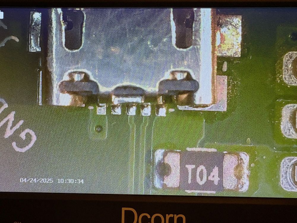
Close-up view of USB connector
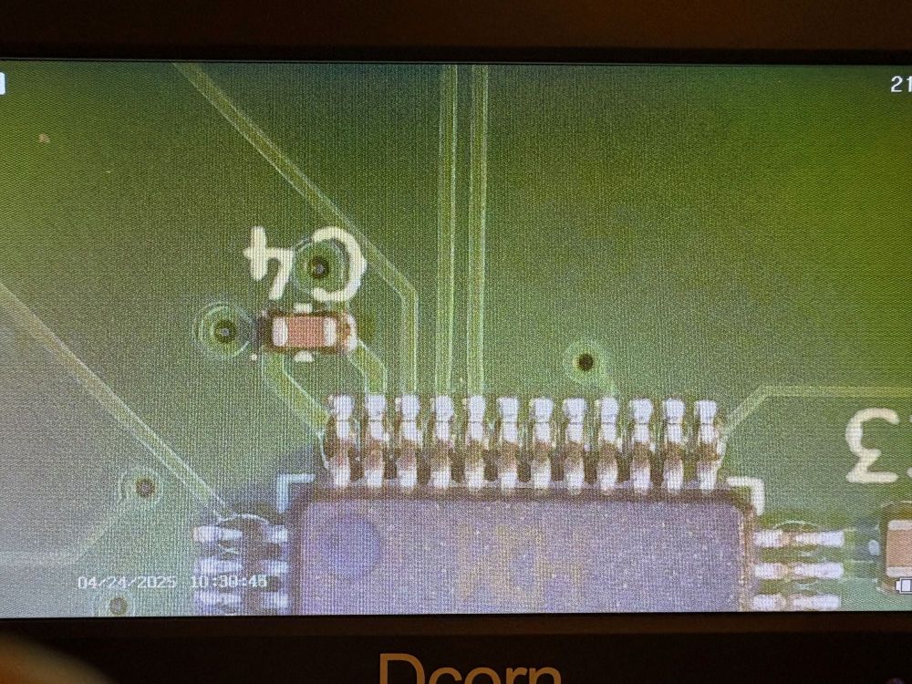
Close up view of MCU pins
I'm kicking myself for not adding test points for USB, and now it doesn't want to enumerate for either TinyUSB or the built-in USB bootloader.
I'm not really sure what to do in this situation; USB is kind of a big deal for what I want to do.
Any thoughts?
24.04.2025 14:35 — 👍 0 🔁 0 💬 1 📌 0

A round TFT display on a round circuit board has a picture of nyan cat on it.
Yay: Part of my PCB works!
Noooooo: USB Does not!
24.04.2025 14:35 — 👍 2 🔁 0 💬 1 📌 0
External oscillator is now working :D
I had to lift it up using hot air, disconnect the enable pad and leave it floating.
I guess it really was active high after all. Whoops.
23.04.2025 20:07 — 👍 0 🔁 0 💬 0 📌 0
Shouldn't I be seeing something from the out pin though?
My first guess was the pin labeled "tri-state" with no other documentation is actually active high instead of active low as in my design.
Or I could just lift it and use the internal oscillator, but still I was certain I got it right :/
22.04.2025 16:24 — 👍 0 🔁 0 💬 0 📌 0
Oh nooooooooooo there's nothing coming from the external oscillatooooorrrrrrrrr!
;_;
22.04.2025 13:04 — 👍 0 🔁 0 💬 1 📌 0
It's a ch32v203 with 128mbit spi flash on board and a connector for a round TFT display.
I had it assembled for me by JLCPCB, so if anything doesn't work its a whole lotta dough down the drain.
At least so far it programs and I get UART output, though the USB connector should've been further out
22.04.2025 11:35 — 👍 2 🔁 0 💬 0 📌 0

A round circuit board with soldered components
PCBs came and this one seems to program.
I’m a bit afraid of checking further in case I made a boat anchor, in which case I would be emotionally devastated for several hours to a day or so.
If I never actually test it then it’s possible everything works.
22.04.2025 00:12 — 👍 3 🔁 0 💬 3 📌 0
No worries; I played around with my footprint until I got something I was happy with.
In fact, the board just finished production and I hope to see it soon.
15.04.2025 11:25 — 👍 1 🔁 0 💬 0 📌 0
Would you mind sharing your footprint?
It looks like you even have the little holes for aligning the connector and everything.
09.04.2025 14:35 — 👍 0 🔁 0 💬 1 📌 0
Ohhhhh! I see it now!
That means I don't have to worry about placing components around the connector which I'm thrilled about.
My only worry would be doing a good enough solder job to survive the mechanical wear, but I'm definitely going to do this.
Much appreciated!
09.04.2025 13:57 — 👍 0 🔁 0 💬 1 📌 0
I'm having a hard time picturing it, do you mind explaining further?
09.04.2025 12:36 — 👍 0 🔁 0 💬 1 📌 0

A round TFT display aligned with a printout of a PCB

A closeup picture of a FPC cable next to its footprint
I have no idea if I’m doing this correctly or if I’m about to make expensive e-waste.
Anybody used these kind of ribbon cables or displays?
07.04.2025 23:51 — 👍 1 🔁 0 💬 1 📌 0
Pointless, but it was fun to try.
04.04.2025 14:42 — 👍 0 🔁 0 💬 0 📌 0
No idea if anyone finds this useful, especially since I need to fold in a few more controllers, but it supports a few as of now:
gc9a01
ili9341
ssd1351
st7735
st7789
st7796
All you need to provide is a few functions to set/clear CS,DC,RST and write to SPI.
03.04.2025 23:44 — 👍 1 🔁 0 💬 0 📌 0
Profile for the LGR YouTube channel. Covering vintage computer hardware, software, and various retro tech oddities. https://youtube.com/@LGR
Nerd, Electronics, PCBs, eINK, ePAPER, ESP32, KiCad, Arduino, SolarHarvesting
Hello everyone! I'm Adrian Black, a retro computer YouTuber who fixes stuff from Portland, Oregon.
Main: youtube.com/@adriansdigitalbasement
Second: youtube.com/@adriansdigitalbasement2
Extras: youtube.com/@adriansdigitalbasementextras
Special Projects Director at @spectrum.ieee.org. Co-author of Hollyweird Science Vol. 1 and 2. Occasional science fiction editor. Maker and Retrocomputician. Feral cat servitor. 5e DM. ADHD. KB1WNR. 65xx. Originally from Dublin.
Experimental Playful Hardware Designer. I made Line Wobbler, which won some awards. Now working on Quantum Jungle ✨🌱🔨
He/him, hi 🦆 “A cinnamon bun in a leather jacket” 🍊 It’s pronounced “young” 🪐 Playful design, mental health, queer anticapitalism, ducks ☀️ Electronics, artgineering, enthusiasm 🎨 @nickyonge everywhere 🌱
he/him/they/them - Tech at Gadgetoid.com, (Micro)Python wrangler at @Pimoroni.com, documenter of Pi’s at pinout.xyz and pico.pinout.xyz, perpetually exhausted parent, possibly some kind of artist, dabble in music… Oh and a ~50% deaf, ADHD mess.
You know what we're here for.
Creative Technologist and award-winning Artist
Speaker
Randomness Sommelier
~from generative dreams to tangible art~
~doing sidequests for a living~
#generativeart #creativecoding #opensource #maker #electronics #penplotter #solarpunk #tinyhouse
General and Embedded Software Engineer that likes to take on weird projects!
LOOKING FOR WORK!
Located in Pittsburgh
Post-Humanist, Feminist, Absurdist
Poly
💜💜💜 Wifey~ @rummik.bsky.social
🖤🖤🖤 Gf~ @softlavendarcow.bsky.social
Electronics, maker, builder, engineer, ham radio (PD4MP), cnc, software development
https://nickstick.nl
Video wizard - NYC
🪩 LCD - Digital Experiences for Leading Brands
⚡️ Flux - Rapidly build interactive sites
🔩 MUN - Fabrication and hardware incubator
Woodworker/farmhand with an unhealthy obsession with computer/game hardware and reverse engineering
Creator of OpenTendo and official installer for MakeMHz
https://linktr.ee/Redherring32
(he/him)
profile image done by David Neal (@reverentgeek.com)
Building gadgets, riding bikes, and fighting the good fight for municipal broadband. Chip designer by day. Some days you're a mountain goat; other days you're a fainting goat. 🐐