
It’s all draw.io. The snapping can be infuriating at times, but after a while you figure out patterns to avoid issues.
You can find the file here: github.com/tomverbeure/....
@tomverbeure.bsky.social
Plays with FPGAs. There can never be enough LEDs. Hardware engineer at Nvidia, but my views here are my own. he/him. Also @tom_verbeure at the woolly elephant and the former bird site
It’s all draw.io. The snapping can be infuriating at times, but after a while you figure out patterns to avoid issues.
You can find the file here: github.com/tomverbeure/....

Diagram of a single channel polyphase filter bank

Diagram of a multi-channel polyphase filter bank

Spectrum of a signal with multiple channels

Spectra of the individual channels at the exit of the channelizer
The Stunning Efficiency and Beauty of the Polyphase Channelizer
tomverbeure.github.io/2026/02/16/P...
Welp, now I'm this again: www.aholme.co.uk/GPS/Main.htm
15.02.2026 00:32 — 👍 2 🔁 0 💬 0 📌 0Looks like the link was broken? Here's the corrected one: tomverbeure.github.io/2026/02/07/C...
08.02.2026 05:56 — 👍 1 🔁 0 💬 0 📌 0Of course! Go for it!
08.02.2026 05:53 — 👍 1 🔁 0 💬 1 📌 0
Block diagram of the complex heterodyne with decimation

Spectrum of real heterodyne before and after

Spectrum of complex heterodyne before and after
Complex Heterodynes Explained
tomverbeure.github.io/2026/02/07/C...

Block diagram of an FIR decimation filter split into 3 separate phases.
Notes about Basic Polyphase Decimation Filters
tomverbeure.github.io/2026/01/25/N...

Repairing a Self-Destructing SRS DG535 Digital Delay Generator
07.01.2026 09:06 — 👍 118 🔁 16 💬 7 📌 1Thanks! SRS must have some kind of test jig to debug those boards in isolation. It would have been nice to at least mention this in the manual (though I probably would have read over it.)
25.12.2025 15:18 — 👍 1 🔁 0 💬 0 📌 0
SRS DG535 folded open

Logic analyzer probes on Z80 of an SRS DG535

Power schematic of SRS DG535

SRS DG535 up and running with new LCD panel
The Scenic Route to Repairing a Self-Destructing SRS DG535 Digital Delay Generator
tomverbeure.github.io/2025/12/24/R...
GPS is a great subject to learn DSP concepts.
12.12.2025 21:06 — 👍 1 🔁 0 💬 0 📌 0Gorgeous! I could watch a 2 hour video where you route that thing. I try to make my PCB routing look nice, but it never comes close this.
08.12.2025 20:55 — 👍 1 🔁 0 💬 0 📌 0I currently don’t have a use for git-pages, but I read the whole thing. That’s a good sign. The documentation and writing style is great.
08.12.2025 16:02 — 👍 1 🔁 0 💬 0 📌 0
Yes, they are! I had never seen these kind of caps before.
wiki.console5.com/wiki/Game_Gear
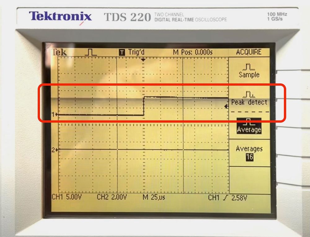
TDS220 screen showing horizontal band screen corruption

PCB inside LCD panel
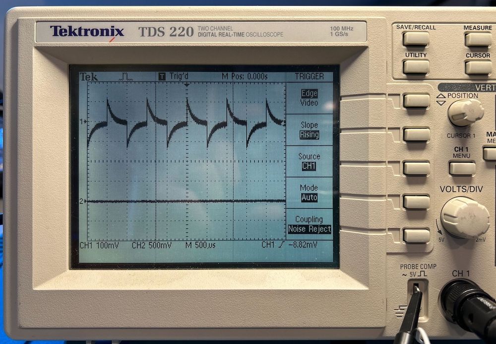
TDS220 screen showing probe compensation waveform that's definitely not right.

TDS220 PSU PCB with arrows to places where there's fluid residue that shouldn't be there.
Fixing LCD Screen Corruption of a Tektronix TDS220 Oscilloscope (and other fixes)
tomverbeure.github.io/2025/11/03/T...
I didn’t know I needed this, and now I do.
02.11.2025 22:30 — 👍 1 🔁 0 💬 0 📌 0
Isotemp OXCO107-10 outside label

Inside of the OCXO, showing a Dewar flash and internal electronics.

Lab bench with oscilloscope, power supply, spectrum analyzer and OCXO

Spectrum with harmonics
Inside an Isotemp OCXO107-10 Oven Controlled Crystal Oscillator
tomverbeure.github.io/2025/10/26/I...
OTOH, I paid for the 16 channel MSO option on my scope, but I’ve never used it. The scope UI is just to terrible and slow compared to a Saleae or DSLogic SW.
22.10.2025 15:39 — 👍 0 🔁 0 💬 0 📌 0The easy of sending data to your PC for decoding and the length of traces. I’ve used a USB logic analyzer to extract the full contents of a large SPI PROM, for example.
22.10.2025 15:36 — 👍 0 🔁 0 💬 0 📌 0I had the 150-in-1. Spent a ton of time on it, but looking back, most of it was building stuff without having a clue about what I was doing. For some circuits, that would still be true today. :-)
20.10.2025 14:09 — 👍 2 🔁 0 💬 0 📌 0Maybe I missed it in the (interesting!) article, but while it mentions radiation intensity, it doesn’t say how it compares to the actual radiation intensity in the LEO where the cubesat resides?
08.10.2025 16:01 — 👍 0 🔁 0 💬 1 📌 0
My new article on Harold Black and the invention of the Negative Feedback Amplifier has just been posted. I start the story with the invention of the telephone in the 1870s, to a patent lawsuit in the 1940s.
Check it out. Let me know what you think.
emedia.digikey.com/eMagazine-Vo...
The article is excellent!
06.10.2025 17:01 — 👍 1 🔁 1 💬 1 📌 0The longevity of the Cyclone II EP2C5 is amazing. 21 years after introduction, it’s still the FPGA that I use most for hobby projects.
05.10.2025 19:32 — 👍 2 🔁 0 💬 0 📌 0
Based on the Unix versions available on tuhs.org, all of this appears to have been introduced in 4.1c BSD. This is the version that adds IPPORT_RESERVED to netinet/in.h and has the TCP/UDP port binding code check it in in_pcbbind in netinet/in pcb.c. In case you think the BSD people thought that this was an elegant idea, let me show you the code: if (lport) { u_short aport = htons (lport) ; int wild = 0; /* GROSS */ if (aport < IPPORT_RESERVED && u.u_uid != 0) return (EACCES) ; [...1 The BSD people knew this was a hack; they just did it anyway, probably because it was a very handy hack in their trusted local network environment. Unix has quietly inherited it ever since.
I'm writing about self-hosting and got wondering why ports <1024 are privileged on Linux, and require you to be root to bind to them.
Found this explanation and couldn't help but laugh. I'd always thought it was a bit of a hack.
utcc.utoronto.ca/~cks/space/b...
Want easy capsense touchpad buttons? Just a PCB & 4 resistors. Coming soon to my Tindie store! If you want to make your own, files are here: github.com/todbot/touch...
This demo in CircuitPython but also works in Arduino w/ my TouchyTouch lib
#circuitpython #capsense #captouch #raspberrypipico
Yeah, if that’s all you’re pulling it should be totally fine.
29.09.2025 22:46 — 👍 1 🔁 0 💬 0 📌 0The 7805 is a linear voltage regulator. Its power consumption will be the current through it times the voltage drop. You have a pretty large drop of 14V, so the heat produced in the regulator could be significant. Something to keep in mind.
29.09.2025 21:25 — 👍 1 🔁 0 💬 2 📌 0
Cecilia Payne-Gaposchkin ✨ figured out what stars are made of ✨ when she was just 25. 🔭🧪
Her PhD thesis basically established the Harvard astro department — at a time when Harvard didn't officially allow woman students.
I wrote this little profile to mark the 100th anniversary of her thesis:
My projects that require custom PCBs are on hold. 🥺
22.08.2025 16:19 — 👍 1 🔁 0 💬 1 📌 0