Yes. Make sure to double check that the pinout/wiring is correct
11.06.2025 16:52 — 👍 2 🔁 0 💬 1 📌 0
Followed by that next moment in the middle of the night when one is trying to sleep and they suddenly ask themselves "Did I forget to repour my ground plane?"
26.04.2025 18:23 — 👍 0 🔁 0 💬 0 📌 0
,..,.
17.04.2025 23:06 — 👍 0 🔁 0 💬 0 📌 0
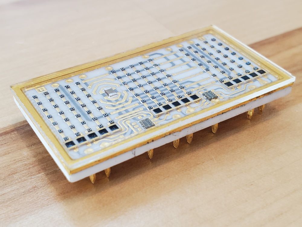
Isometric projection view of the ceramic module.
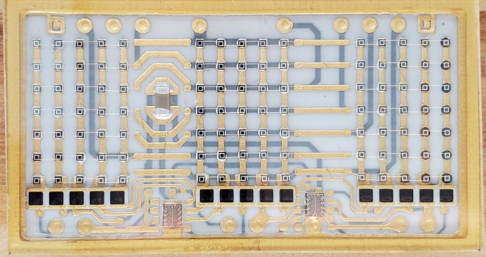
Top view of the ceramic module. The LED dies for each alphanumeric character are arranged in a 5x7 pattern. There are two IC dies at the bottom of the module. The black squares are possibly resistors. The dark grey rectangular object in the middle left of the module is a ceramic capacitor.
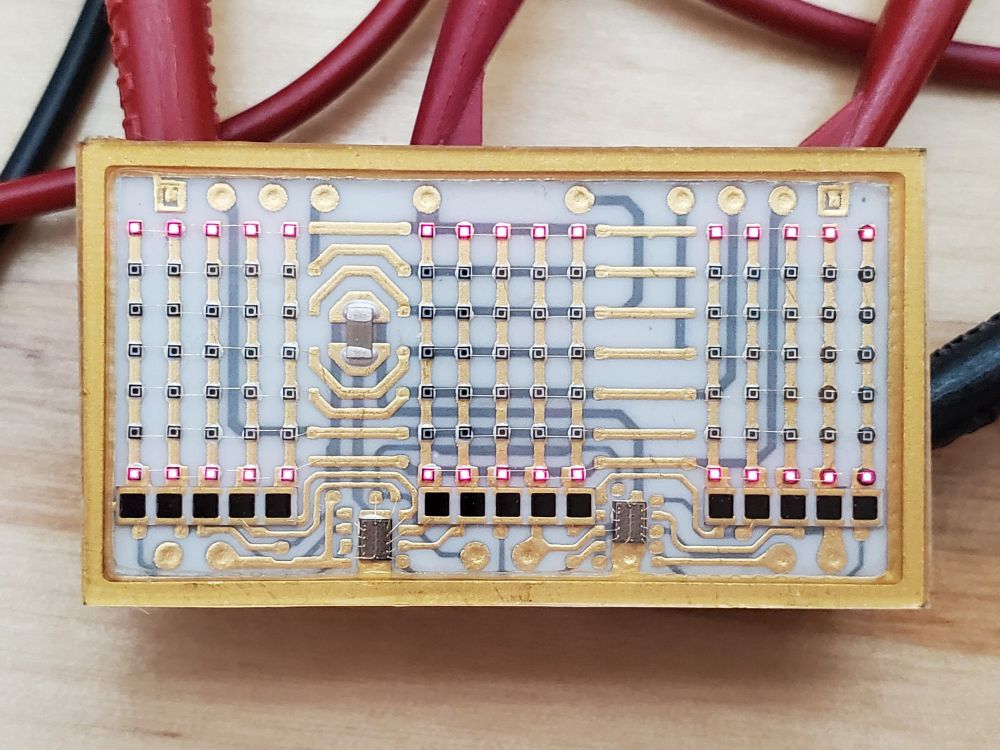
The module with power applied. LEDs in rows 1 and 7 are on.
I recently got this mil-spec ceramic hybrid alphanumeric LED display module. Hopefully I'll be able to figure out how to interface with it in a reasonable amount of time. It likely will require some sort of serial interface though so hopes aren't high. Neat thing to look at though.
17.04.2025 20:02 — 👍 7 🔁 0 💬 1 📌 0
Is the converter a TPS63070 or similar variant?
02.04.2025 18:17 — 👍 1 🔁 0 💬 1 📌 0
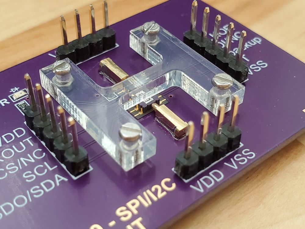
The pins of the IC are being aligned to the board's pads by the pogo pins.

The acrylic cover pushes down on the IC so that its pads make contact with the board's pads.
I made a breakout board for a realtime clock IC featuring an embedded TCXO. The IC is temporarily held in place with pogo pins for alignment, and a piece of acrylic is used to help press the IC onto the pads of the board. This allows me to program the IC for use in another PCB project.
07.03.2025 14:11 — 👍 6 🔁 0 💬 1 📌 0
Interesting. I would assume, at least for professional equipment, the manufacturer would rather the user buy their 4-port model or switch matrix than just have the ability to easily use software on a lower tier model.
04.02.2025 22:55 — 👍 0 🔁 0 💬 0 📌 0
Oof. Hopefully that clock wasn't expensive.
28.01.2025 17:01 — 👍 0 🔁 0 💬 0 📌 0
Grasping at straws here but maybe try putting a load on it and see if the output voltage becomes 5v. Some regulators need a minimum load to correctly output the set voltage.
28.01.2025 16:43 — 👍 1 🔁 0 💬 1 📌 0
Yes. It's good enough to be a substitute for a press fit implementation.
13.01.2025 13:08 — 👍 1 🔁 0 💬 0 📌 0
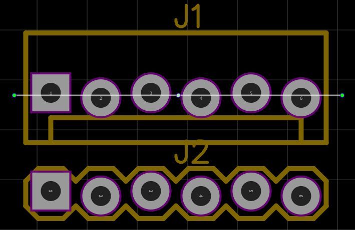
Screenshot example of a footprint using offset through-hole pads in a layout program from a random forum
One way of dealing with the alignment issue of soldering headers - if you have control over the PCB design - is to make the holes offset from one another such that the pins of the header will be snug against their respective through hole pads.
13.01.2025 03:14 — 👍 2 🔁 0 💬 1 📌 0
Thank you. Yes, I designed the PCBs myself. They were made by OSHPark.
23.12.2024 00:18 — 👍 0 🔁 0 💬 0 📌 0
No problem. Hopefully you'll be able fix it without much hassle
23.12.2024 00:17 — 👍 1 🔁 0 💬 0 📌 0
My initial approach would be Physical integrity of the USB Connector -> Power rails -> Clock sources -> USB Controller
22.12.2024 22:09 — 👍 1 🔁 0 💬 1 📌 0
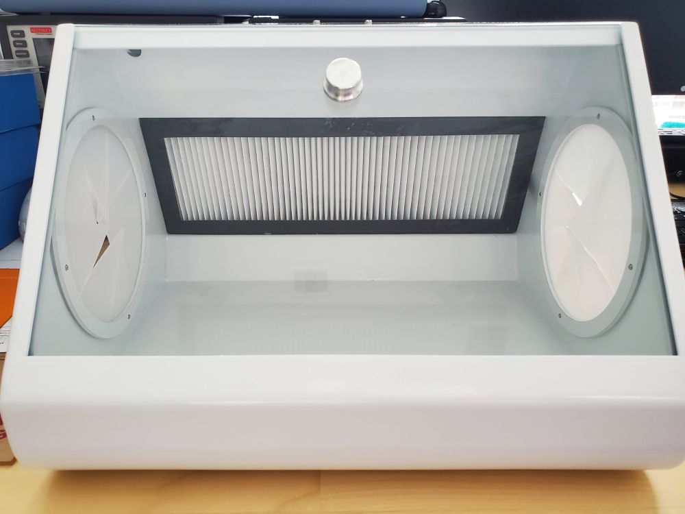
Front view of the box which shows the viewing glass as well as the filter in the back in front of the intake fans
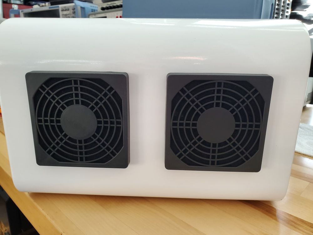
Back view of the box looking at the modified fans to take in air through a filter to create positive pressure
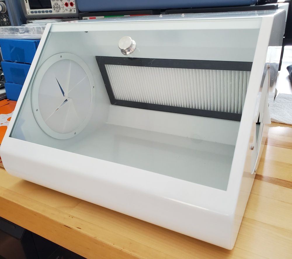
Angled view of the box which shows area to place hand into
My lab room is usually dusty so I got a dental dust box and reversed the fans (for positive pressure) to create a pseudo "clean room" box for certain electronics assembly/testing procedures which require a more dust free environment.
20.12.2024 14:28 — 👍 1 🔁 0 💬 0 📌 0
Exactly. The circuitry was limited to the center of the flexible printed circuit board. The rest of the board was void of any parts except for some thin meandering traces to act as a make-shift deformation sensor.
17.12.2024 01:37 — 👍 1 🔁 0 💬 0 📌 0
For the prototype, I remember cutting the tennis ball in half and then making a circular flexible printed circuit board whose circumference extended up to the outside edge of the ball. The ball is just glued been together. Soccer ball may be harder because it still has to be air tight.
17.12.2024 01:21 — 👍 1 🔁 0 💬 1 📌 0
I had a similar idea in college but it turned out to be a dud due to the amount of deformation the ball undergoes when it is in play. The battery is the biggest problem. I remember my prototype efforts were cut short when the battery ignited.
17.12.2024 01:03 — 👍 1 🔁 0 💬 1 📌 0
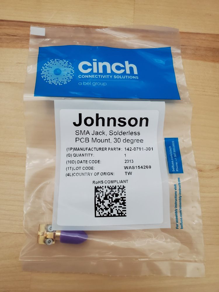
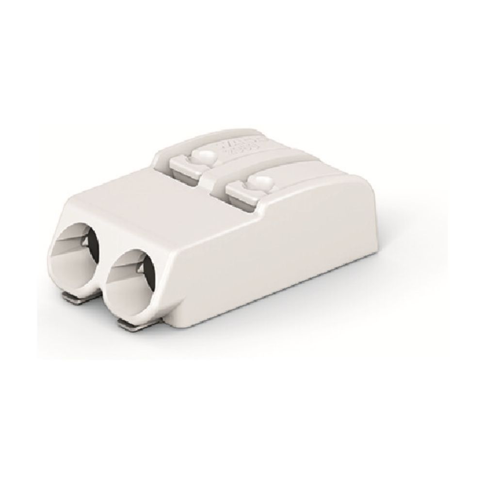
Connector in original packaging.
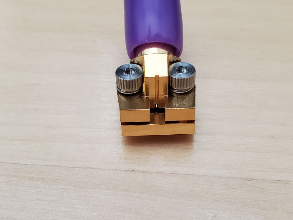
Connector back side with view of signal pin protruding just below the connector body but above the bottom mounting plate.
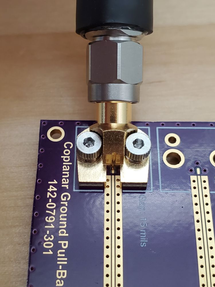
Connector mounted onto PCB
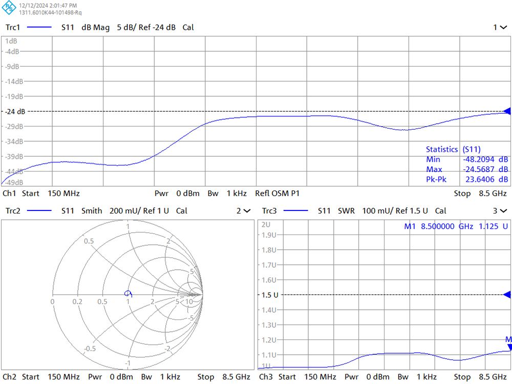
Return loss of RF Connector is quite good.
I got my hands on one of those solderless mid-board launch 30 degree RF connectors. This is for future use in messing around with designing a PCB using distributed elements without having to solder connectors for testing. The initial "best guess" mounting footprint shows good return loss.
12.12.2024 20:59 — 👍 4 🔁 0 💬 0 📌 0
My last guess here for the time being. Lol. Is it for measuring directional power?
11.12.2024 17:41 — 👍 0 🔁 0 💬 1 📌 0
With the diodes there my thought would be some kind of variable attenuator assuming a two-port system with the 2-pin header being in place for supplying the bias voltage. Less likely something like a switch or balanced mixer.
11.12.2024 17:05 — 👍 0 🔁 0 💬 1 📌 0
Is the bottom right a quadrature hybrid coupler?
11.12.2024 16:21 — 👍 0 🔁 0 💬 1 📌 0
YouTube video by EEVblog
EEVblog #1064 - Soldering Irons OLD vs NEW
I would suggest getting an iron that uses tips which have the heater integrated as the response to load is quicker and the temperature is generally more accurate.
youtu.be/scvS2yeUH00?...
22.11.2024 17:19 — 👍 2 🔁 0 💬 1 📌 0
Been in a similar situation before. Are you able to make the front panel out of a different material like PCB?
19.11.2024 18:12 — 👍 0 🔁 0 💬 0 📌 0
🇳🇱🇪🇺Father, husband, electronics engineer, runner. I love low power and solar energy harvesting circuits. I share my failures too. Concerned about climate. From Amersfoort, the Netherlands. http://paypal.me/jrsikken
Everything space & RF. Amateur radio operator (EA4GPZ / M0HXM). PhD in Mathematics from Univ. Autónoma de Madrid. he/him
Passionate about everything related to electronics and robotics.
Electronics freelancer when the sun rises and hobbyist when the sun falls.
Sarcastic book lover, maker, and irrepressible electronics tinkerer. Exploring CNC anything, designing circuit boards, being dragged kicking and screaming into coding and raising unique kiddos. Currently on a mission to ignore politics and make cool stuff!
Make your design a Reality.
Tag pcbway to be featured at our page!
🔶 PhD student @ Dept of analytical chemistry | Palacký University | Olomouc, CZ
🔶 instrumentation engineer
🛠️ hardware archeologist
🛠️ obsolete device innovator
#️⃣ #hardwarearcheology #ChemSky #microfluidics
💬 ENG / UA / CZ
📝 opinions are my own
I do firmware, I love learning!
I make things with computers.
Used to cause trouble at AWS, IBM, and FT Labs. Forged in the fires of Redweb Labs (which were mostly my fault)
https://smt.codes
PCB enthusiast/Very familiar with PCB production process & cost/Sales engineer in Shenzhen Lensuo/Cats lover/Swimming lover/Snooker
Website: www.lensuo.com
He/Him - Electronics Engineer, Consultant, Owner of Soley Engineering (soleytech.com),
FOSS supporter, high speed digital design enthusiast
Electrical engineer. RF electronics, IC design, radars, FPGA, programming. hforsten.com
Retro gamer and Atari fan. The Jaguar is the best console ever made, and the Falcon is the best home computer.😁
Also own and enjoy Commodore, Acorn and other great retro stuff.
RF prototyping, design and test equipment. Creator of Gquipment.
www.gquipment.com
official Bluesky account (check username👆)
Bugs, feature requests, feedback: support@bsky.app